This tutorial is designed to give you a quick start at learning how to use the CodeWarrior® IDE for Win32/x86 programming. These are the topics covered in this chapter:
In this tutorial, you will create a ray-tracing application program. Ray tracing is a method of rendering three-dimensional scenes with photo-realistic accuracy, including shading, shadows, and reflection of light. It operates by tracing the path from your eye to objects, and from the objects to the sources of light. The process is highly processor-intensive, requiring a significant amount of computation for each pixel displayed.
 TIP
TIP For best results when running your application, have your monitor set to display at least 16 thousand colors.
To give you some useful experience, the user interface for the program will be a Microsoft Foundation Classes (MFC) application, and the ray-tracing engine will be a dynamic link library (DLL). For more information, see:
The IDE User Guide contains general information on using the CodeWarrior IDE.
Before you begin, copy the RayTracer folder from the CodeWarrior Reference CD to your hard disk. You'll
find it in the CodeWarrior Examples folder, in the Win32 Examples sub-folder under Win32 Tutorial. Open the copy of the folder on your hard disk, start up the
CodeWarrior IDE, then follow these steps to set up the project:
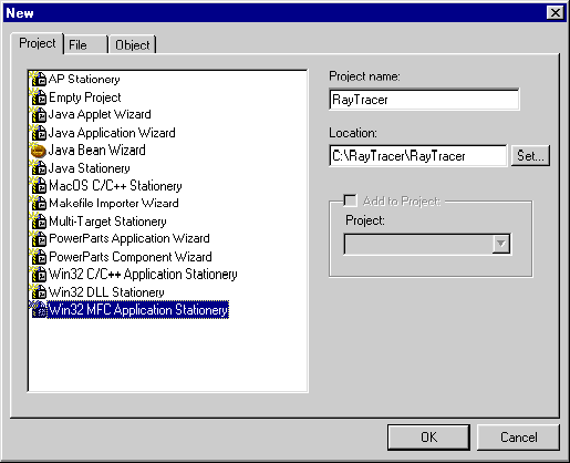
Choose File > New. The New dialog appears, as shown in Figure 3.1.
2. Select the project category.
Select Win32 MFC Application Stationary from the list in the Project tab. Type RayTracer.mcp in the Project name field. By convention, a project name ends with .mcp. You may also use the Location text box or Set button to choose a different location to store the project. Then
click OK.
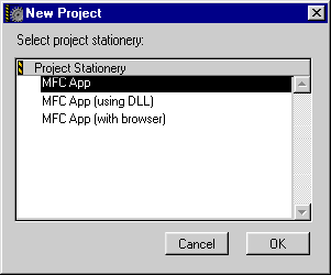
Choose the MFC App project stationery from the Project Stationary area of the New Project window, as shown in Figure 3.2. Then, click OK.
4. Add source files to the project.
When the IDE finishes opening your project, a window bearing the
project name you typed in the Project name text box of the New dialog appears. Click Sources in the project window, then choose Projet > Add Files. The Select files to add dialog appears, as shown in Figure 3.3. Navigate to the RayTracer folder, select Ray1.cpp, and click
Add. The Add Files dialog appears, as shown in Figure 3.4. Add the file to all targets by enabling all options in the Targets area, then click OK.
Select files to add dialog: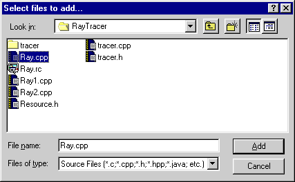
Add Files dialog: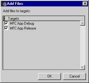
5. Remove the source file placeholder from your project.
Select main.cpp in the Sources group of the project window and choose Edit > Delete. Your project
window should now look like Figure 3.5.
Project window with source file added: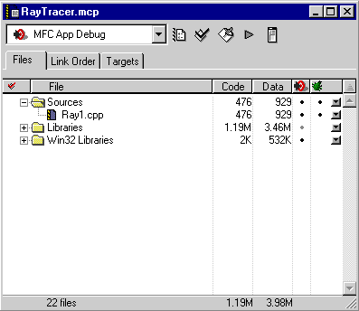
6. Display the Target Settings dialog.
Choose Edit > Target Settings, where Target is the name of the project's currently selected
target. Since we have selected an MFC App target for our RayTracer
project, the command appears as MFC App Debug Settings. The Target Settings dialog appears.
TIP You can also display the Target Settings dialog by clicking the Target Settings button, which is the left-most button in the project window.
7. Select the x86 Target panel.
Click x86 Target in the Target Settings Panels area of the Target Settings dialog. The x86 Target setting panel appears, as shown in Figure 3.6.
Target Settings dialog showing the x86 Target panel: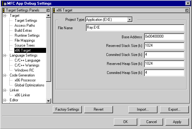
8. Specify the name and type of output file.
Make sure Application (EXE) is selected in the Output File Type list box, and type Ray.exe into the File Name text box. Then, click OK to confirm your settings and close the dialog.
Choose Project > Make. The CodeWarrior IDE will then compile and link your program.
Choose Project > Run. If all goes well, an empty window titled Ray the Tracer appears that you can manipulate on your screen: move it, resize
it, maximize it, minimize it, and close it.
You have just built the first version of Ray the Tracer, which at this point only draws an empty window on the screen. Let's take a look at the code.
In the Ray.mcp project window, double-click the file Ray1.cpp to open an edit window displaying the contents of the file. At
the top of the source file, the following line appears:
#include <afxwin.h>
The header file afxwin.h defines the most common of the Microsoft Foundation Classes (MFC).
MFC is an object-oriented interface to Win32, consisting of classes
either used directly in programs or from which subclasses can
be derived.
class CTracerWindow: public CFrameWnd
This line defines a class for our main window, CTracerWindow.
This class is derived from the MFC class CFrameWnd, which implements the behavior of a standard Win32 window. The
only member function in our derived class is the constructor,
CTracerWindow. Looking down a little further at the definition of this function,
you can see that it simply calls the Create function, inherited from the base class CFrameWnd, to create the window.
class CTracerApp: public CWinApp
defines a class derived from CWinApp, the MFC class representing a Win32 application. Its only member
function is InitInstance, called during application startup. Our definition of this function
creates a new window of class CTracerWindow and assigns it to member variable m_pMainWnd, inherited from the base class CWin-App. The next two statements display the window and update (paint)
its contents on the screen. Finally, InitInstance returns TRUE to indicate that it has succeeded.
This last line in the source file,
CTracerApp TracerApp;
may look innocuous, but it actually is responsible for the entire execution of the program. Here's what MFC does behind the scenes:
1. It declares a variable of type CTracerApp.
2. The constructor for this object calls the InitInstance function we just looked at.
3. InitInstance, in turn, creates the window.
4. The CTracerApp constructor then automatically initiates a message loop, which
runs for the duration of the application.
5. Finally, the message loop receives input events (clicks and keystrokes) from the mouse and keyboard and dispatches it to the code that handles these events.
Currently, our program does not contain code to handle events, so it cannot do very much. However, MFC provides defaults that allow the user to manipulate the window on the screen in all the usual ways: move it, resize it, maximize it, minimize it, or close it. That's actually quite a lot for such a simple application. The main thing is, it's a working program. If getting started is the hardest part of a project, that part, at least, is done.
Now that we're finished examining the code, close the Ray1.cpp window.
Most Win32 programs use resources to define menus, icons, and other objects that the program uses.
In this phase, we will add a text resource file to our application
project.
Alternatively, you can use the CodeWarrior Resource Editor application to work with resources. This application allows you
to manipulate resources visually.
If the project window is not already open, choose File > Open and open RayTracer.mcp.
Double-click Ray.cpp in the Sources group of the project window. An edit window appears displaying
the contents of the file.
3. Include the header file defining the resource identifiers.
#include <afxwin.h>
at the beginning of the source code, add the line
#include "resource.h"
4. Modify the code to create its window from a resource.
In the definition of the constructor function CTracerWindow, replace the statement
Create(NULL, _T("Ray the Tracer"), WS_OVERLAPPEDWINDOW, rectDefault);
// Create the window with attributes from ray.rc LoadFrame(IDR_MAINFRAME);
In Win32 resource files, each resource has an integer or string
identifier. The LoadFrame function (inherited from base class CWndFrame) looks for resources with a specified identifier, then creates
a window based on the information in those resources. In this
case, it will find the window's menu, a string for the window's
title, and an icon, all of which have the identifier IDR_MAINFRAME.
But where do these resources reside? In a resource file, of course.
In this case, the file is named Ray.rc. To make the resources available, we must add the Ray.rc file to the project.
5. Add the resource file to the project.
Click Sources in the project window, then choose Project > Add Files. The Select files to add dialog appears, as shown in Figure 3.3. Navigate to the RayTracer folder, select Ray.rc, and click Add.
The Add Files dialog appears, as shown in Figure 3.4. Add the file to all targets by enabling all options in the Targets area, then click OK.
Let's take a moment to look at the contents of the resource file.
Open the resource file in an edit window by double-clicking its
name, Ray.rc, in the project window. The file contents begins with the following
line:
#include "resource.h"
This includes the same header file as Ray.cpp. Next is a line reading:
IDR_MAINFRAME MENU DISCARDABLE
This introduces the definition of the program's main menu. The lines that follow specify the menu's contents. In this case, since this is a main menu, its items are the names of the individual menus in the window's menu bar.
POPUP, which are followed by a BEGIN and END, define the menus attached to each of the menu bar items.
MENUITEM lines between BEGIN and END specify the items on each menu.
MENUITEM line is the identifier for the command that will be sent to the
application when that menu item is selected.
STRINGTABLE definition specifies strings that the program uses. The one labeled
IDR_MAINFRAME is used automatically as the title of the window when the program
calls LoadFrame.
Now we're ready to build the new version of the program.
As before, choose Project > Make to compile and link the modified version of the program.
Run the program to verify that it displays the menu bar for the
window. You may notice that all commands are grayed out except
for the Exit command on the File menu. This is because the program does not yet contain any code
to handle these commands; MFC is clever enough to recognize this
and disable the commands that the program has left not implemented.
Now we are ready to make the program more interesting by handling the commands on its menus.
If the project window is not already open on your screen, choose
File > Open and open RayTracer.mcp.
2. Replace the source file Ray1.cpp with Ray2.cpp.
Select the Sources group in the project window, then choose Project > Add Files. The Select files to add dialog appears, as shown in Figure 3.3. Navigate to the RayTracer folder, select Ray2.cpp, and click
Add. The Add Files dialog appears, as shown in Figure 3.4. Add the file to all targets by enabling all options in the Targets area, then click OK. Next, select Ray1.cpp in the project window and remove it by choosing Edit > Delete.
3. Display the contents of the new source file.
Double-click Ray2.cpp in the Sources group of the project window. An edit window appears displaying
the contents of the file.
Looking at the code, you can see that we have added several new
member functions to class CTracerWindow, such as OnPaint() and ViewFront(). OnPaint(), an MFC member function inherited from the base class CFrameWnd, will be called whenever our window receives a paint message,
indicating that the contents of the window need to be repainted
on the screen. The other new functions, such as ViewFront(), handle menu commands that the user chooses from View menu
Following the function declarations is the line
DECLARE_MESSAGE_MAP()
This is an MFC macro that creates the message map for the window. The message map tells MFC how to map incoming
messages sent to the window into calls to the appropriate member
functions. The actual definition of the message map is accomplished
by the following series of macro calls below the CTracerWindow class declaration:
BEGIN_MESSAGE_MAP(CTracerWindow, CFrameWnd) ON_WM_PAINT()
ON_COMMAND(ID_VIEW_FRONT), ViewFront)
ON_COMMAND(ID_VIEW_LEFT), ViewLeft)
ON_COMMAND(ID_VIEW_RIGHT), ViewRight)
ON_COMMAND(ID_VIEW_BACK), ViewBack)
END_MESSAGE_MAP()
The ON_WM_PAINT macro specifies that our member function OnPaint() is to be called whenever the window receives a paint message.
The next four lines identify the member functions that handle
each of the four commands on the View menu. The identifiers defined in the resource header file Ray.rc, such as ID_VIEW_FRONT, are used to connect each menu command with the corresponding
member function via the ON_COMMAND macro.
Right after the message map are the lines
CDC Picture; CBitmap Bitmap;
These are declarations for two MFC objects: a display context and a bitmap. Together, they allow us to draw a picture and display it in our window. How this actually works is beyond the scope of this tutorial, but we can still have a peek at the code.
Down a little further is the function definition for the member
function OnPaint() of class CTracerWindow. This is the handler function for paint messages, the part of
the program that actually puts something on the screen. This function
calls GetClientRect() to get the dimensions of the window's client area (the area the
program can draw into), then copies the bitmap (which will eventually
contain our ray-traced image) into the window, using the function
BitBlt().
 NOTE
NOTE The functions GetClientRect() and BitBlt() belong to the Win32 application program interface (API). Here,
they are used as MFC member functions. MFC member functions generally
map directly into the corresponding API calls. If MFC were not
being used, the API functions would be called directly.
The remaining member functions we've added to CTracerWindow (ViewRight(), ViewLeft(), ViewFront(), and ViewBack()) will eventually implement the actual ray-tracing procedures.
For now, they're simply left empty.
Use Project > Make to compile and link this latest version of the program.
When you run the program, a black box 200 pixels wide by 200 high
appears in the middle of the window. This is the (currently empty)
bitmap that the BitBlt() function in our OnPaint() function copied into the window. Notice also that the From Front, From Left, From Right, and From Back commands on the View menu are enabled, since there are now defined functions to handle
them (even though all of these functions are currently empty).
The (admittedly meager) user interface of our ray-tracing application is now complete. All that is missing is code to do the actual ray tracing. Unless you have a Ph.D. in math (or can at least remember Algebra 2), writing this code yourself will be rather difficult. Fortunately, you have a friend (coincidentally named Ray) who offers you a ready-made, generic ray-tracing engine written in C++.
"The beauty of it," says Ray, "is that this engine is totally system-independent. The truth is, it knows nothing about the hardware or operating system it's running on."
We get suspicious when programmers talk about beauty and truth.
But in this case, Ray does not exaggerate. The tracer engine defines
a class RayTracer with a single abstract virtual member function named SetPixel(). All you have to do to use the engine is derive a class from
RayTracer and define its SetPixel() function. Sounds easy enough.
You think that you might want to transport this code some day, such as when Windows 2005 comes along, so you decide to keep the tracer engine as independent as possible of your user-interface code.
The solution is to place the code in a dynamic link library (DLL). A DLL contains code that does not stand on its own as
an application, but instead is used by other applications. It
can be kept completely separate, residing in a different file
from the applications that use it.
Creating a DLL is very similar to creating an application, so we will not elaborate much on the individual steps except where they differ from the ones we looked at earlier. Here's how to create a DLL from the ray-tracing engine:
The New dialog appears, as shown in Figure 3.1.
2. Select the project category.
Select Win32 DLL Stationary from the list in the Project tab. Type TracerDLL.mcp in the Project name field. By convention, a project name ends with .mcp. You may
also use the Location text box or Set button to choose a location on your hard disk to store the project.
Then click OK.
Select Win32 C++ DLL from the Project Stationary area of the New Project window, as shown in Figure 3.2. Then, click OK.
4. Add the DLL's source file to the project.
When the IDE finishes opening your project, a window bearing the
project name you typed in the Project name text box of the New dialog appears. Click Sources in the project window, then choose Projet > Add Files. The Select files to add dialog appears, as shown in Figure 3.3. Navigate to the RayTracer folder, select tracer.cpp, and click
Add. The Add Files dialog appears, as shown in Figure 3.4. Add the file to all targets by enabling all options in the Targets area, then click OK.
5. Remove the source file placeholder from your project.
Click the file x86_Win32DLL.cp in the Sources group of the project window and choose Edit > Delete.
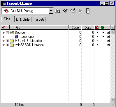
Your project window should now look like Figure 3.7.
6. Display the Target Settings dialog.
Choose Edit > Target Settings, where Target is the name of the project's currently selected
target. Since we have selected a C++ DLL target, the command appears
as C++ DLL Debug Settings. The Target Settings dialog appears.
TIP You can also display the Target Settings dialog by clicking Target Settings, which is the left-most button in the project window.
7. Select the x86 Target panel.
Click x86 Target in the Target Settings Panels area of the Target Settings dialog. The x86 Target setting panel appears, as shown in Figure 3.6.
8. Specify the name and type of output file.
Make sure Dynamic Link Library (DLL) is selected in the Output File Type list box, and type Tracer.dll into the File Name text box. Then, click OK to confirm your settings and close the dialog.
Choose Project > Make to compile and link the DLL. This command creates two files:
Tracer.dll, the actual DLL, containing all the code and resources included
in the project.
Tracer.lib, a static library for linking client programs to the DLL. Adding
this file to a project makes the contents of the Tracer DLL available
to another program (an application or even another DLL).
The DLL communicates with its client programs by exporting some of its functions and variables with the declaration modifier
__declspec(dllexport). This modifier specifies that the declaration that follows is
to be made available to the DLL's client programs. To see an example,
double-click the source file tracer.cpp in the project window to open the file in an edit window. Choose
Search > Find to search for the string __declspec. (Note the double underscore at the beginning of the name.) You
will find the lines
#ifdef __INTEL__ __declspec(dllexport)
#endif
void RayTracer::Trace(Object *ObjectList,
LightSource *LightList, int w, int h,
Vector ViewPos)
This says that if the code is being compiled for an Intel processor,
the function Trace is to be exported as part of the DLL's client interface. Choose
Search > Find Next and you will find several more exported names.
Now that we actually have some ray-tracing code (in a DLL) and
a user interface (in an application), the only thing left to do
is link them together. A header file named Tracer.h came with your friend Ray's tracing engine. You can add this
file to your Ray.mcp project to define the interface from your application to the ray
tracing engine. After that, it is only a matter of adding a little
"glue" code to hold it all together.
If the project window is not already open, choose File > Open and open RayTracer.mcp.
2. Add the interface library file to the project.
Click Sources in the project window, then choose Project > Add Files. The Select files to add dialog appears, as shown in Figure 3.3. Navigate to the TracerDLL folder, select Tracer.dll and Tracer.lib, then click Add. The Add Files dialog appears, as shown in Figure 3.4. Add the file to all targets by enabling all options in the Targets area, then click OK.
3. Add the appropriate source file to the project.
Select Sources in the project window, then choose Projet > Add Files. The Select files to add dialog appears, as shown in Figure 3.3. Navigate to the RayTracer folder, select Ray.cpp, and click
Add. The Add Files dialog appears, as shown in Figure 3.4. Add the file to all targets by enabling all options in the Targets area, then click OK.
4. Remove the old source file from your project.
Select ray2.cpp in the Sources group of the project window and choose Edit > Delete.
Double-click Ray.cpp in the project window to open an edit window and view the code.
The first new section is shown in Listing 3.1.
Object definitions for the r ay-tracing program:
// Some serious balls
Sphere Object1(0.0, 0.0, 0.0, 5.0, 1.0, 0.5, 0.1, 0.5);
Sphere Object2(4.0, 2.0, -4.0, 2.0, 0.3, 1.0, 1.0, 0.5);
Sphere Object3(-4.0, 2.0, -4.0, 2.0, 0.3, 1.0, 1.0, 0.5);
// And a floor
BoundedPlane Object4(0.0, 1.0, 0.0, 6.0, -100.0, 100.0,
  -10000, 10000, -1000.0, 1000.0, 0.5, 0.5, 0.7, 0.2);

// And a ceiling
BoundedPlane Object5(0.0, 1.0, 0.0, -12.0, -100.0, 100.0,
  -10000, 10000, -1000.0, 1000.0, 0.7, 0.5, 0.5, 0.0);

// And a couple of lights
LightSource Light1(10.0, 10.0, -10.0, 50000.0, 50000.0, 50000.0);
LightSource Light2(-5.0, 4.0, 10.0, 30000.0, 30000.0, 30000.0);
This code defines objects in the virtual world that we are going
to ray-trace. Each line is a constructor for a class exported
from the Tracer.dll library and defined in the header file Tracer.h. You'll see the results when you run this final version of the
program.
Next, you will see a definition for a class named MyTracer, which is derived from class RayTracer. The only member it defines is a function named SetPixel(). This function is called once for each pixel in an image rendered
by the ray tracer, to set the pixel to the proper color in the
destination bitmap. The destination could be the screen, a file,
or a printer; it makes no difference to the ray-tracing engine.
void CTracerWindow::ViewLeft()
{
  Vector View;

  // Set up view position to the left of the scene
  View[X] = -15.0;
  View[Y] = 0.0;
  View[Z] = 0.0;
  Ray.Trace(&Object1, &Light1,
       PICTURE_WIDTH, PICTURE_HEIGHT, View);
  InvalidateRect(NULL);
}
Somewhat further down in the source file, you will find the definition
of function ViewLeft(), as shown in Listing 3.2. This function is called when a user chooses View > From Left; a similar function is provided for each of the other commands
on the menu. Each of these commands views the same set of objects
from a different angle; the corresponding functions set up a vector
to define the viewing position, then call the ray-tracing engine's
Trace function to generate the image as viewed from that point. The
Trace function will call back to our SetPixel() function to set each pixel in the image to the appropriate color.
Finally, we call the Win32 function InvalidateRect() to tell the system that part of our window has changed and must
be repainted. This results eventually in a call to our OnPaint() function to display the newly generated bitmap.
Now we are finally ready to build the full application.
Choose Project > Make. The CodeWarrior IDE will then compile and link the ray-tracer
program.
Choose Project > Run. Ray the Tracer displays the same window, menu, and black box
as before. But this time, when you select one of the commands
from the View menu, the program displays a ray-traced image of something that
resembles a weirdly colored water molecule. (It may take some
time for the program to compute the image; be patient.)
If you would like to experiment further with the code, read the
comments in the Tracer.cpp source code to learn how the object constructors work. You can
then try moving objects around, changing their colors, and so
forth, to produce an infinite variety of images. If you are a
bit more ambitious, you can try adding object classes of your
own, such as a cylinder, cone, or pyramid.