This chapter discusses each of the settings panels that affect code generation for Win32/x86 development. By modifying the settings for the individual items within a panel, you can control the compiler, linker, and other aspects of code generation.
Specific details about how the compiler and linker work for Win32/x86 development, such as compiler pragmas, linker symbols and so forth, is found in "C and C++ for Win32."
The sections in this chapter are:
Each target in a CodeWarrior® project has its own individual settings. These settings control a variety of features, such as compiler options, linker output, error and warning messages, and so forth. These are modified settings through the Target Settings window, where Target is the name of the project's currently selected target. This interface is fully explained in the IDE User Guide.
In brief, the compiler and linker behavior for a particular target
is controlled by modifying settings in the appropriate settings
panels in the Target Settings window. To open any settings panel, choose Edit > Target Settings, where Target is the current target in the project. Or, click
the Target tab in the project window and double-click the target of interest.
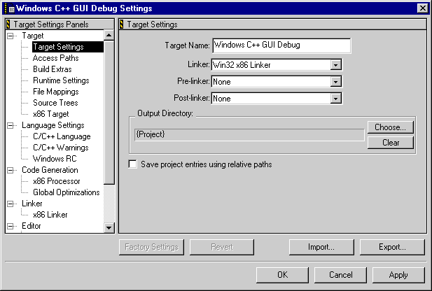
The Target Settings window appears, as shown in Figure 8.1.
Select the settings panel you wish to examine from the list in the Target Settings Panels area. You can then modify the settings to suit your needs.
When you modify the settings on a panel, you can restore the previous
values by clicking Revert. To restore the settings to the factory defaults, click Factory Settings.
 TIP
TIP Use project stationery when you create a new project. The stationery has all settings in all panels set to reasonable or default values. To create your own stationery file with your preferred settings, modify a new project to suit your needs, then save it in the stationery folder. See the IDE User Guide for details.
This section discusses panels specific to Win32/x86 development, and the purpose and effect of each setting. The panels are:
Settings panels of more general interest are discussed in other CodeWarrior manuals. Table 8.1 lists several panels and where you can find information about them.
Where to find information on other settings panels:
| Panel |
Manual |
|---|---|
The Target Settings window contains a Target Settings panel. The window and the panel, while similarly named, are not the same. The window displays all panels, one at a time. The Target Settings panel is one of those panels.
The Target Settings panel, shown in Figure 8.2, is perhaps the most important panel in the CodeWarrior IDE. This is the panel where you pick your target. When you select a linker in the Target Settings panel, you specify the target operating system and/or chip. The other panels listed in the window will change to reflect your choice.
Because the linker choice affects the visibility of other related panels, you must set your target before you can specify other target-specific options, like compiler and linker settings.
The Target Settings panel is not the same as the x86 Target panel. You specify the target in the Target Settings panel. The x86 Target panel is used to control other target-specific settings.
Use the Target Name field to set or change the name of a target. When you use the Targets view in the project window, you will see the name that you have set.
The name you set here is not the name of your final output file. It is only the name you assign to the target. The name of the final output file is set in the x86 Target panel.
Choose a linker from the items listed in the Linker pop-up menu. For Win32/x86, use Win32 x86 Linker.
Some targets have pre-linkers that perform work on object code before it is linked. There is no pre-linker for Win32/x86 development.
Some targets have post-linkers that perform additional work (such as object code format conversion) on the final executable. There is no post-linker for Win32/x86 development.
This is the directory where your final linked output file will be placed. The default location is the directory that contains your project file. Click the Choose button to specify another directory.
To add two or more files with the same name to a project, enable
this option. When this option is enabled, the IDE includes information
about the path used to access the file as well as the file name
when it stores information about the file. When searching for
a file, the IDE combines access path settings with the path settings it includes for each project
entry.
When this option is disabled, the IDE only records information about each project entry's file name. Hence, each project entry must have a unique name. When searching for a file, the IDE only uses Access Paths.
The Clear button clears the Output Directory choice.
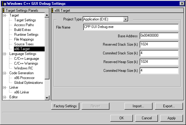
The x86 Target panel, shown in Figure 8.3, is where the name of your final output file is specified.
The settings available in this panel depend on the type of project you are creating.
This list-box specifies the type of output file to generate. These types are:
Application (EXE)-stand-alone application
Dynamic Link Library (DLL)-dynamic link library
Library (LIB)-static library
This field controls the name of the application or library file to be generated.
This field specifies the preferred address for loading the application
or DLL. The default is 0x00400000.
Applications and DLLs load faster when loaded at the preferred address. However, if the default address is not available, Windows will relocate them to an empty address.
This field specifies the amount of virtual address space reserved for the stack. The default is 1024 K.
This field specifies the amount of memory actually allocated to the stack on loading. This amount automatically increases as needed during execution, up to the reserved stack size. The default is 4 K.
This field specifies the amount of virtual address space reserved for the dynamic memory heap. The default is 1024 K.
This field specifies of memory actually allocated to the heap on loading. This amount automatically increases as needed during execution, up to the reserved heap size. The default is 4 K.
This option determines whether an import library is generated. The field associated with the option allows the output name for the import library to be set. The File Name field triggers simultaneous changes in the import library field while being edited.
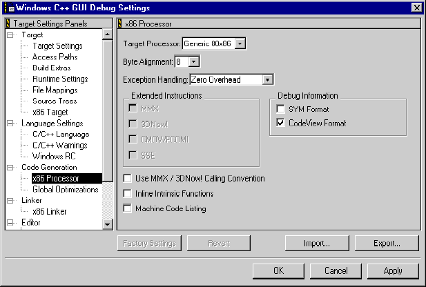
The x86 Processor panel, shown in Figure 8.4, is where settings related to code generation for the Win32/x86 platform are controlled.
This list-box specifies the processor for which to generate object code. The available are:
Generic 80x86-generates instructions that execute on Intel® 80386, Intel 80486,
all Intel Pentium processors, and compatible processors
Pentium-generates instructions that execute on all Intel Pentium and
compatible processors
Pentium Pro-generates instructions that execute on Intel Pentium Pro and
compatible processors
Pentium II-generates instructions that execute on Intel Pentium II and compatible
processors
Pentium III-generates instructions that execute on Intel Pentium III and
compatible processors
AMD K6-generates instructions that execute on Advanced Micro Devices
K6 processors
Specifies the alignment boundary for structure and class members. Each member is aligned on a multiple of either the specified alignment or the size of the member, whichever is bigger.
For example, if you set the byte alignment to 16 bytes and the
member size to 2 bytes, it will be aligned on a 16-byte boundary;
if the byte alignment is 4 bytes and the member size is 8 bytes,
it will be aligned on a 8-byte boundary. If the byte alignment
is set to 1, all members will start on the next available byte,
with no padding between members. Setting Byte Alignment to 4 or 8 can improve execution speed, but with a penalty in
memory usage if structures have wasted space.
The Exception Handling list-box allows switching between handling schemes.
The Extended Instructions area contains options controlling the generation of instructions for specific processors. Which, if any, options are available depends on the processor selected in the Target Processor list-box.
http://developer.intel.com/vtune/cbts/pproopt/TRYFIRST/0R.HTM
or on the Intel Developer web site at:
http://developer.intel.com
http://developer.intel.com/technology/itj/Q21999/ARTICLES/art_2.htm
or on the Intel Developer web site at:
http://developer.intel.com
The Debug Information area contains options controlling the generation of symbolic debugging information.
 NOTE
NOTE To generate CodeView symbolics for debugging, you must enable the CodeView Format option in the x86 Processor panel and the Generate CV Info option in the x86 Linker panel.
Enabling the Use MMX/3DNow! Calling Conventions option enables the generation of 3DNow! extensions with further optimization for speed.
To learn more about optimizing for AMD K6 or AMD Athlon processors, see "Targeting AMD Processors."
The CodeWarrior x86 C/C++ compiler provides intrinsic functions to generate inline x86 instructions. These intrinsic functions execute faster than other functions because the compiler translates them into inline assembly instructions instead of function calls. A list of the function calls available for inlining is listed in Figure 8.5.
Enable this option to tell the compiler to inline these functions.
Functions available for inlining under the x86 C/C++ compiler:// memory allocation
void * _alloca (size_t n)
// block memory operations
void * memmove (void *dest, const void *source, size_t n)
void * memcpy (const void *dest, const void *source, size_t n)
char * strcpy (char *dest, const char *src)
size_t strlen (const char *s)
// floating point math
double sin (double x)
double cos (double x)
double tan (double x)
double atan (double x)
double atan2 (double x)
double acos (double x)
double asin (double x)
double log10 (double x)
double log (double x)
double exp (double x)
double pow (double x)
double sqrt (double x)
double fabs (double x)
// x86 hardware operations
void _outp (unsigned short port, unsigned char val)
void _outpw (unsigned short port, unsigned short val)
void _outpd (unsigned short port, unsigned long val)
unsigned char _inp (unsigned short port)
unsigned short _inpw (unsigned short port)
unsigned long _inpd (unsigned short port)
// memory allocation
void * _alloca (size_t n)


// block memory operations
void * memmove (void *dest, const void *source, size_t n)
void * memcpy (const void *dest, const void *source, size_t n)
char * strcpy (char *dest, const char *src)
size_t strlen (const char *s)
// floating point math
double sin (double x)
double cos (double x)
double tan (double x)
double atan (double x)
double atan2 (double x)
double acos (double x)
double asin (double x)
double log10 (double x)
double log (double x)
double exp (double x)
double pow (double x)
double sqrt (double x)
double fabs (double x)

// x86 hardware operations
void _outp (unsigned short port, unsigned char val)
void _outpw (unsigned short port, unsigned short val)
void _outpd (unsigned short port, unsigned long val)
unsigned char _inp (unsigned short port)
unsigned short _inpw (unsigned short port)
unsigned long _inpd (unsigned short port)
// memory allocation void * _alloca (size_t n) // block memory operations void * memmove (void *dest, const void *source, size_t n) void * memcpy (const void *dest, const void *source, size_t n) char * strcpy (char *dest, const char *src) size_t strlen (const char *s) // floating point math double sin (double x) double cos (double x) double tan (double x) double atan (double x) double atan2 (double x) double acos (double x) double asin (double x) double log10 (double x) double log (double x) double exp (double x) double pow (double x) double sqrt (double x) double fabs (double x) // x86 hardware operations void _outp (unsigned short port, unsigned char val) void _outpw (unsigned short port, unsigned short val) void _outpd (unsigned short port, unsigned long val) unsigned char _inp (unsigned short port) unsigned short _inpw (unsigned short port) unsigned long _inpd (unsigned short port)
NOTE Support for intrinsic functions is not part of the ANSI C or C++ standards. They are an extension provided by the CodeWarrior compilers.
 WARNING!
 Type case is important for intrinsic functions, as is getting the function prototype correct. In the absence of prototypes, the compiler may generate incorrect code for these functions.
This option generates a mixed listing of your source files that includes both the original source code and the machine code generated by the CodeWarrior IDE. You can use the disassembler to obtain a listing of machine code, but without the accompanying source code. For more information on the disassembler, refer to the IDE User Guide.
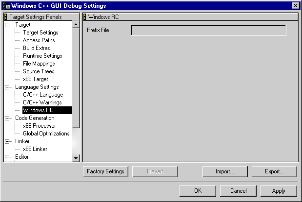
The Windows RC panel, shown in Figure 8.6, allows you to specify a file that is scanned for resource information during the compilation of your code. See "Creating Win32 Resources" for more information about working with resources.
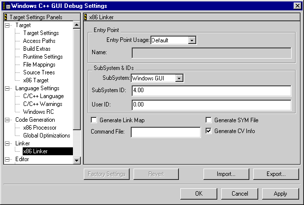
The x86 Linker panel, shown in Figure 8.7, is where you control settings related to linking your object code into final form, be it executable, library, or other type of code.
These items in this panel are:
This list-box specifies the name of the project's main entry point:
Default-the usual choice. The linker sets the entry point automatically,
depending on the type of project, as shown in Table 8.2.
User Specified-type the entry point name into the Name field.
WARNING! Use this setting only in projects that do not use C or C++ run-time library functions; otherwise, the run-time library will not be initialized and library functions may fail.
For an example of when this setting is useful, see "DLL Initialization."
| For this project type |
The linker sets the entry point to this symbol |
|---|---|
This field specifies the name of the symbol that provides the
entry point for the module. This field is only available if the
User Specified setting is selected in the Entry Point Usage list-box.
Select a setting from the SubSystem list-box as follows:
¯ If _main is defined, the subsystem is Windows CUI.
¯ If _WinMain@16 or _wWinMain@16 is defined, the subsystem is Windows GUI.
Native-use this setting for drivers and system executables Windows GUI-use this setting for applications using the Win32 graphical user
interface Windows CUI-use this setting for Win32 console applications
This field identifies a specific version of the selected subsystem. The value of this setting is a floating-point number, with the integer part giving the major ID and the fractional part the minor ID:
For other subsystems, the subsystem ID is undefined.
This field specifies a version number for your application or library, which will appear in the header of the output file. You can set it to any floating-point value you wish.
When enabled, this option generates a link map listing the items the linker processed.
When enabled, this option generates a SYM file containing symbolic debugging information in SYM format.
When enabled, this option stores symbolic debugging information in the object file (whether an executable application or a DLL) in CodeView format.
This field specifies the name of the linker command file, an optional text file containing additional commands for controlling the operation of the linker.
NOTE To generate symbolic debugging information in either SYM or CodeView
format, you must turn on the corresponding settings in both the
x86 Processor and x86 Linker project settings panels.
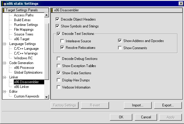
The x86 Disassembler panel, as shown in Figure 8.8, controls the information displayed during disassembly.
The Decode Object Headers option determines whether the assembled file lists any header information in the disassembled output.
The Show Symbols and Strings option determines whether the disassembler lists the symbol table for the disassembled module.
The Decode Text Sections option determines whether text sections appear in the disassembled output.
When this option is enabled, the following additional options become available:
The Decode Debug Sections option determines whether to include debug symbol information in the disassembled output.
The Show Exception Tables option determines whether the disassembler outputs exception tables for the disassembled module.
The Show Data Sections option determines whether the disassembler shows data sections in the disassembled output.
The Display Hex Dumps option determines whether unstructured hex dumps appear in the disassembled output.
The Verbose Information option determines whether the disassembler shows additional information about certain types of information in the linker file.
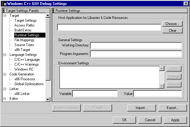
The Runtime Settings panel presents settings for configuring the runtime environment that your project will run in while it is under the debugger's control.
Environment variables listed in this panel are created when the project is launched and removed when the project finishes executing. The IDE ensures that these environment variables have no effect on previously defined or global environment variables.
This field allows you to specify the application used to drive the libraries for debugging purposes. When the library is debugged, the program specified in this field will be launched to provide the host environment for your library code. Click the Choose button to navigate to the program file, or click Clear to remove any settings in this field.
This field specifies the default directory to which the project will have access.
Specifies command-line text to pass to the project when it is launched by the IDE debugger.
This area contains items that control the IDE environment.
Variable field to the list of environment variables and assign it the
value in the Value field.
Value field.
Variable field.
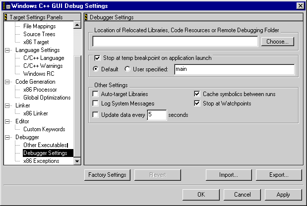
The Debugger Settings panel is used to select the tools to use for debugging your project. Additionally, you can import pre-defined debugger settings from an XML file by clicking Import, or export the settings in this panel by clicking Export.
Launches a program before running the project under the debugger's
control. Click Choose to navigate to the folder in which the program is stored. This
option is most useful when debugging a piece of software that
acts as a plug-in or extension to another program.
This option controls whether or not the debugger stops when a temporary breakpoint is reached. When enabled, the following two radio buttons become available:
Controls the display of messages in the debugger's log window. If selected, messages about the actions the debugger takes while controlling your application appear in the log window.
NOTE This feature is only available when debugging on Windows.
This option allows you to decide whether libraries will be automatically targeted for debugging.
This option allows you to choose the rate at which data updates occur.
When enabled, this option caches symbolic debugger information.
This option allows you to decide whether or not the debugger will stop at watchpoints.
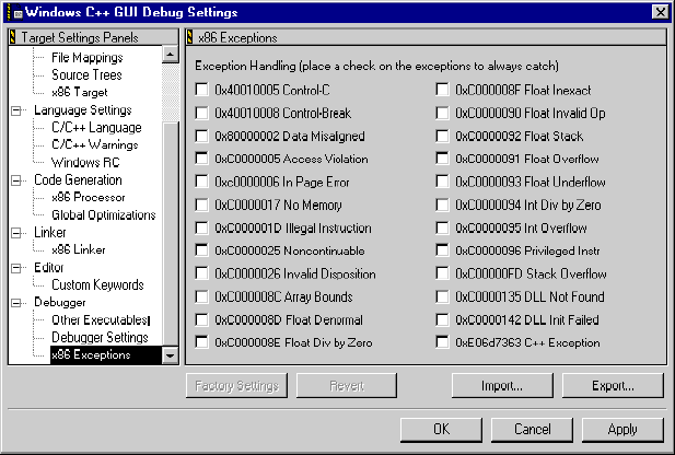
The x86 Exceptions panel, shown in Figure 8.11, lists all the exceptions that the debugger is able to catch. If you want the debugger to catch all the exceptions, enable all of the options in this panel. However, if you prefer to handle only certain exceptions, enable only those options that reflect the exceptions you prefer to handle.
Additionally, you can import pre-defined exceptions settings from an XML file by clicking Import, or export the settings in this panel by clicking Export.